Following board can be used for any board with working SPI on ISP connector but is primary targeted for copters.
Biggest difference between Crius AIOP v.1 and v.2 is 16Mb dataflash on board. ArduCopter have same capability but Crius v.1 or Hobby King clone AIO clone don’t.
Dataflash logs can be really useful during tuning of your copter so I decide to extend standard boards with this new capability.
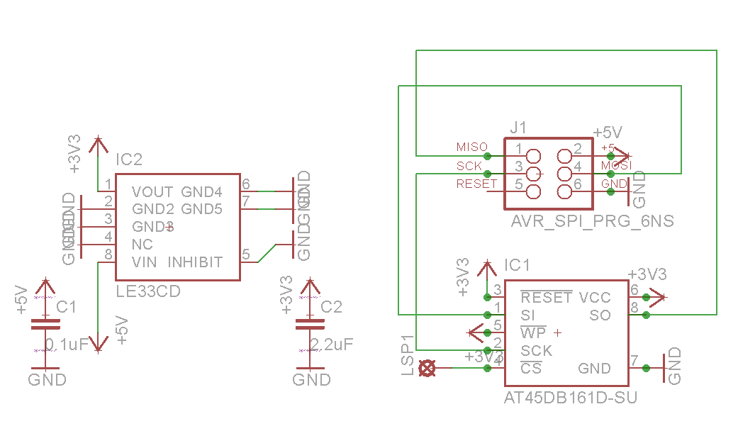
Result is small PCB board with LE33 voltage regulator (and two capacitors) to provide 3.3V VCC voltage for memory and Atmel AT45DB161D memory with 2MB (or 16Mb) capacity. Memory is SPI so we can create board as attachment to ISP connector on AIO board.
There is also one more wire needed for CS – I used pin 33 (originally used for camera trigger from RC receiver, not used in most cases) which is connected by wire with board.
How it looks can be seen here :
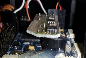
Result attached to Multiwii Pro with Mega 2560 XCopter board
It is my first SMD so sorry for quality. Fortunately, SOIC 8 and 1206 sized parts can be soldered at home with reasonable soldering stuff without major problem. Also DPS can be done by photo etching easily (see other blog post for detail).
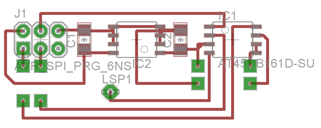
So here is schematic, board and pdf for your DPS :
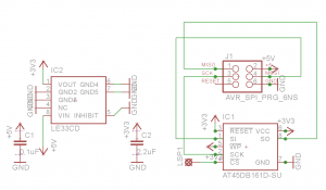
ISP Memory Schematic

Board
ISP Memory DSP
Also you need short update in your MegaPirate NG code (for arduino look for standard DataFlash library)
1. locate Dataflash folder in Libraries
2. change pins settings in DataFlash_CRIUS_AIOP2.cpp code
// arduino mega SPI pins
#define DF_DATAOUT MOSI // MOSI
#define DF_DATAIN MISO // MISO
#define DF_SPICLOCK SCK // SCK
#define DF_SLAVESELECT 33 // SS (PB0)
#define DF_RESET 32 // RESET (PG0)
where DF_SLAVESELECT is your chosen pin on board. DF_RESET should lead to unused pin although is not used for board.
3. set your config to Crius V2
#define PIRATES_SENSOR_BOARD PIRATES_CRIUS_AIO_PRO_V2
Compile code, put your board on your copter and done.
Now you have dataflash logs capabilities and you can measure your vibrations or other stuff on copter.
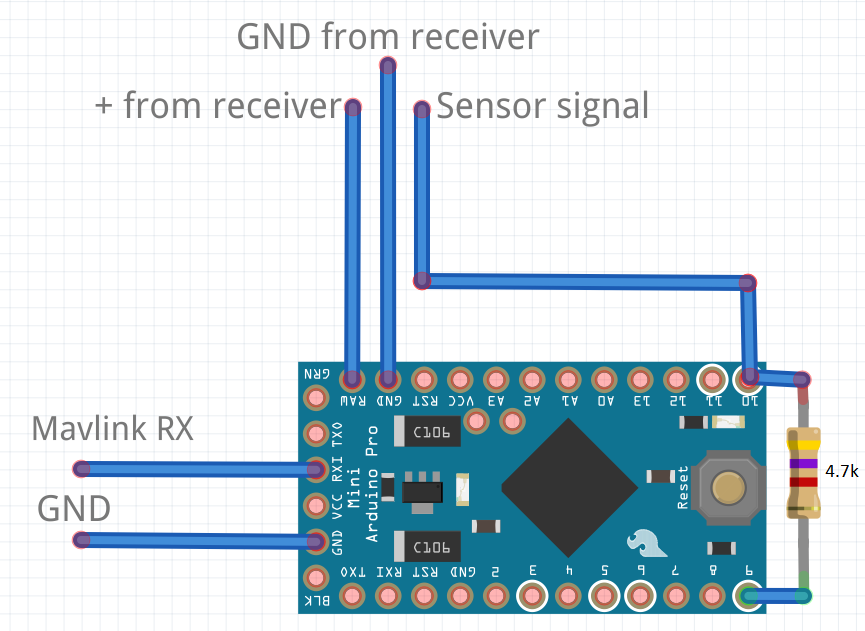 Code using one hardware serial for reading telemetry from Mavlink board (ArduCopter or MegaPirateNG) and output data into Jeti as software serial. Here is video to show Alarms https://www.youtube.com/watch?v=bKOuzuYNKlU